Overview
Transistors that work together in a circuit—such as in differential amplifiers, current mirrors, or push-pull output stages—often need to be closely matched. While integrated circuit (IC) manufacturers can produce matched pairs on a single silicon die with near-perfect uniformity, discrete transistors of the same type can vary significantly. As [Learn Electronics Repair] explains in a recent video, achieving consistent performance requires measuring key parameters like DC current gain (hFE) or saturation voltage (Vce(sat)). Without matching, one transistor may carry more current than its partner, leading to inefficiency, thermal runaway, or premature failure. This guide covers why matching matters, how to do it, and common pitfalls to avoid. Note that transistor matching is distinct from impedance matching, which aims to maximize power transfer between a source and load.

Prerequisites
Before diving into the process, make sure you have the following:
- Basic understanding of transistor operation (BJT or MOSFET).
- Digital multimeter (DMM) with a transistor test socket (hFE measurement capability).
- Breadboard and jumper wires for building a test circuit.
- Power supply (e.g., 5V or 9V DC).
- Resistors (e.g., 1kΩ, 10kΩ) and a few transistors of the same type to test.
- Optional: Data logging system (Arduino with analog inputs) for automated collection.
- A stable, room-temperature environment to avoid temperature drift.
Step-by-Step Instructions
1. Identify the Matching Parameters
The first step is to decide which parameter(s) need to be matched for your specific circuit. Common choices include:
- DC current gain (hFE or β): Important for current mirrors, differential pairs, and Darlington configurations.
- Base-emitter voltage (Vbe): Critical for temperature compensation and biasing in long-tailed pair amplifiers.
- Saturation voltage (Vce(sat) or Vds(on)): Required when transistors are used as switches and must drop minimal voltage.
For most hobby projects, matching hFE is sufficient. However, if you are designing precision analog circuits (e.g., an op-amp input stage), you may need to match both hFE and Vbe.
2. Set Up a Test Circuit
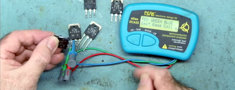
You can measure parameters with a simple test jig. For BJT hFE measurement, many multimeters have a built-in socket: insert the transistor, select hFE mode, and read the value directly. However, for more accurate and consistent results, build the circuit shown below (for an NPN transistor):
  +Vcc (5V)
    |
    R (10kΩ)
    |
    C (collector)
    |
    B (base) --- Rbase (100kΩ) --- GND
    |
    E (emitter) --- GND (via a small resistor optionally)
This forces a known base current (Ib ≈ (Vcc - 0.7V) / Rbase) and measures Ic across Rc. Calculate hFE = Ic / Ib. For PNP, use mirrored polarity. For Vbe matching, simply forward-bias the base-emitter with a constant current (e.g., 1 mA) and measure Vbe with a voltmeter.
3. Measure and Record Values
Take ten to twenty transistors of the same type and test each one. Use the same circuit, same temperature, and same supply voltage. Record the results in a table. For example:
- Insert Transistor #1 into test jig.
- Allow 10 seconds for settling.
- Note hFE (or Vbe) value.
- Remove and label the transistor.
- Repeat for all samples.
If using an Arduino, you can automate this with a multiplexer and ADC—just be sure to calibrate the reference voltage.
4. Select Matching Pairs
Once measurements are collected, look for pairs whose values are within the required tolerance. For example, if you need a differential pair with hFE mismatch < 5%, group transistors whose hFE values fall within a 5% band. The same logic applies to Vbe: for a current mirror, you usually want Vbe within 1–2 mV at the same collector current. A common rule of thumb:
- For audio or general-purpose circuits: hFE within ±10%.
- For precision analog (op-amp input): hFE within ±1% and Vbe within ±0.5 mV.
Mark matched pairs with numbers or labels. If you have many devices, sort them from lowest to highest and take adjacent ones.
Common Mistakes
- Ignoring temperature effects: Transistor parameters shift with temperature. Always measure at the same ambient temperature and allow devices to settle.
- Measuring at a different operating current than the final circuit: hFE and Vbe vary with Ic. Use a test current close to the actual bias current.
- Using only a multimeter hFE socket: While convenient, these often measure at a fixed, low collector current (e.g., 1–2 mA) which may not represent your circuit conditions.
- Assuming two transistors with the same hFE are perfectly matched: They may have different Vbe or reverse leakage. For critical applications, match multiple parameters.
- Forgetting about mechanical stress: Soldering a transistor can change its characteristics. Measure before soldering, or use sockets.
- Confusing matching with impedance matching: As mentioned earlier, matching transistors is about equalizing device parameters, not about adjusting source/load resistance for maximum power transfer.
Summary
Matching transistors is essential for circuits where balanced operation is crucial. By understanding which parameter to match (hFE, Vbe, or Vce(sat)), building a consistent test setup, and carefully measuring multiple samples, you can create reliable matched pairs for differential amplifiers, current mirrors, and bridge circuits. Avoid common pitfalls like temperature drift and mismatched operating points. With practice, you’ll be able to select devices that work in harmony, improving efficiency and preventing early failure. For more advanced projects, consider using a curve tracer or dedicated transistor matching adapter.